Condensation Control in Environmental Testing: Preventing False Failures
Electronics fail in environmental testing for reasons that are often not the temperature itself. Humidity, dew point, condensation physics and the thermal gradient across a board determine whether a test reveals a real weakness or an artefact of the chamber.
Electronics fail in environmental testing for reasons that are often not the temperature itself. Humidity, dew point, condensation physics and the thermal gradient across a board determine whether a test reveals a real weakness or an artefact of the chamber.
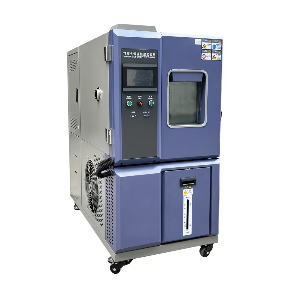
Applying that to a real purchase is easier when the equipment comes from a supplier that builds rather than assembles. 150L Climate Test Chamber is a typical example of a machine where the specification sheet is only half the story, because the fabrication and commissioning route determines how the numbers behave in service.
What to verify before you specify
1. Dew point controls what the board sees
A chamber at 40℃ and 95% RH puts moisture on the board. A chamber at 40℃ and 40% RH does not, even though the temperature is identical. The dew point, not the relative humidity reading, is the relevant quantity.
2. Condensation is a physical process with a timescale
Water vapour needs time to condense on a cold surface. A short dwell at high humidity does not reproduce a day of condensation in service, so the dwell has to be justified against the real use case.
3. Thermal gradients cause warpage and stress
A board that is clamped at the edges and exposed to a rapid ramp experiences differential expansion. Fixture design has to represent the real mounting or the test is measuring the fixture.
4. Material properties change across the range
Adhesives, solder joints and plastics have different coefficients of thermal expansion, and a rapid cycle loads the joints in a way that a slow ramp does not. The standard ramp rate is part of the stress being applied.
5. Power cycling during test is often essential
Real electronics operate while they are being stressed. A chamber that holds a steady temperature while the device is unpowered misses the failures that only appear when the board is live and warm.
6. Recovery and inspection complete the cycle
Visual inspection, electrical test and functional check after the cycle are where the actual failure is identified. The standard defines the sequence, and it needs to be followed exactly.
Mistakes that show up in the acceptance report
- Using relative humidity as a proxy for dew point in the test profile.
- Testing an unpowered board and then wondering why the failures look different.
- Clamping a board rigidly in a way that no real assembly clamps it.
- Using a ramp rate much faster than the standard without justification.
Manufacturing capability as a risk-reduction strategy
When a qualification programme has a fixed window, the biggest risk is not the test failing. It is a delivery date moving.
Engineering drawings, chamber fabrication, control cabinet wiring and commissioning all sit under one roof, so a specification change during the project is absorbed by the factory rather than passed between suppliers.
Owning the production route means the critical path is the one we control. Non-standard chamber sizes, unusual instrumentation and special test profiles do not become a procurement problem.
The quality file travels with the machine. IQC at material intake, IPQC during assembly and OQC before crating mean the acceptance decision at your laboratory is traceable to our production floor.
- In-house Manufacturing: Every machine is engineered, welded, assembled and tested under one roof. Two production plants control tolerances from raw sheet steel to final calibration.
- OEM & ODM Engineering: Drawings, PLC logic, instrumentation and chamber geometry are developed in-house, so non-standard chamber sizes and test profiles ship without external dependencies.
- Full In-House Calibration: Temperature, humidity, pressure and load cells are calibrated on our own accredited benches before shipment, with certificates issued per unit.
- QC at Every Stage: IQC, IPQC and OQC gates sit between material intake, welding, assembly and dispatch. Nothing leaves the line without a signed inspection record.
How the equipment is produced
The production route below is the one every HAOEN machine follows. It is listed because the steps a manufacturer controls are the steps that determine whether your laboratory receives a machine that performs as specified on the day it is commissioned, and still performs two years later.
- Engineering Drawing — Chamber geometry, load frame, airflow and instrumentation are modelled and reviewed before any steel is cut.
- Material Intake — Sheet metal, compressors, sensors and electrical parts pass incoming inspection against incoming QC checkpoints.
- Cutting & Bending — CNC cutting and press braking form the chamber body, liner and door frame to millimetre drawings.
- Welding & Forming — TIG and robot welding seal the chamber, followed by stress relief and surface treatment.
- Assembly & Wiring — Refrigeration, electrical cabinets, sensors and control panels are installed and wired to the schematic.
- Debugging & Calibration — Commissioning runs temperature, humidity, vibration and load profiles; data is logged per unit.
- Packing & Documents — Crating, manuals, certificates and the QC file are completed and sealed for dispatch.
- Delivery & Support — Shipment tracking, on-site installation and operator training are arranged with local partners.
Equipment referenced in this guide
- 150L Climate Test Chamber — Climate Test Chamber, manufactured in-house with per-unit calibration.
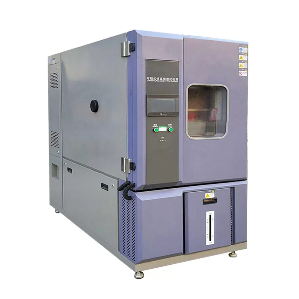
- 1000L Climate Test Chamber — Climate Test Chamber, manufactured in-house with per-unit calibration.
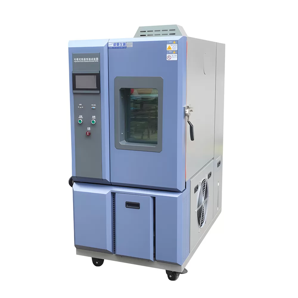
- 225L Climate Test Chamber — Climate Test Chamber, manufactured in-house with per-unit calibration.
Conclusion
Specification is where a procurement process starts, but it is not where the result is decided. The variables that separate a repeatable test from an arguable one are the ones the manufacturer controls: the geometry of the chamber, the tightness of the weld, the stability of the control loop and the discipline of the calibration bench. Those are the variables worth asking about, because they are the ones that will still be there when the instrument is three years old and a colleague asks why the new machine and the old one give different numbers on the same specimen.
If you have a specification in front of you that has a profile, a volume and a tolerance, send it over. Our engineers will respond with a configuration, a lead time and the specific items in the manufacturing route that will affect your result.